What is Camshaft Phasing, and Why Does it Matter?

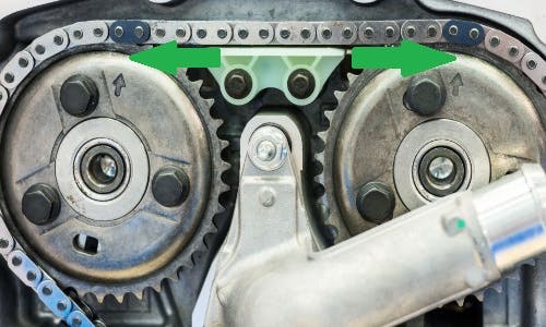
For any camshaft to regulate the valves on any engine effectively and correctly, all camshafts need to be indexed to various reference points to establish the correct timing of the valves, and the image above shows one of several methods of establishing and maintaining the proper phasing or indexing of an intake and exhaust camshaft with respect to each other.
In this example, the timing/indexing marks are the two small arrows stamped into the camshaft sprockets, and in designs like this, simply aligning the timing marks with the coloured links (as shown here with the two green arrows) establishes and maintains proper phasing between the two camshafts.
Although the timing chain sprocket on the crankshaft is not shown here, it will have a similar mark that aligns with a chain link that has a different colour to avoid confusion and mistakes during engine assembly. Thus, installing the timing chain correctly by keeping the slack (in the chain) on the return side of the chain, aligning all the timing marks with all the coloured links automatically establishes and maintains the correct phasing between a) both camshafts, and b) between both camshafts and the crankshaft.
Other methods of maintaining proper camshaft phasing include-
- timing belts used in conjunction with timing marks on the engine: this is a common method on engines with a single overhead camshaft
- gear trains known as “timing gears”: this is the most common method to drive camshafts that act on the valves via pushrods
- various combinations of timing belts and gear sets, with the most common arrangement being a timing belt that drives one camshaft from the crankshaft, with the belt-driven camshaft driving a second camshaft with indexed or phased gears. This method is common on in-line engines with separate intake and exhaust camshafts
On many V-type engines with overhead camshafts, each bank of cylinders has separate intake and exhaust camshafts, meaning that the engine has four camshafts in total. In these engines, the lobes on the camshaft that act on the intake valves in cylinder #1 are indexed to both a reference point on the crankshaft and to a reference point on the intake camshaft on the opposite bank of cylinders. In addition, the intake and exhaust camshaft on each bank of cylinders are also phased with respect to each other.
For diagnostic purposes, the phasing of camshafts with respect to both each other and the crankshaft is known as “Crankshaft/Camshaft Correlations”, and all modern engines use several sensors to provide real-time data inputs to one or more microprocessors (aka control modules) that monitor the various correlations continuously. Note that even minute miscorrelations between camshaft(s) and the crankshaft can have dramatic negative effects on engine performance, fuel consumption, exhaust emissions, and general drivability.
To prevent the issues mentioned above from occurring, sophisticated monitoring and control software in several engine management systems assess the seriousness of any detected miscorrelations, and when a miscorrelation exceeds a maximum allowable threshold, one or more implicated control modules will set one or more dedicated camshaft/crankshaft correlation-related fault codes. Depending on the nature and severity of a detected miscorrelation, other actions may include illuminating the MIL (CHECK ENGINE) warning light, and/or restricting throttle inputs both as a safety measure, and to protect the engine against possible mechanical damage that may result from serious crankshaft/camshaft miscorrelations.
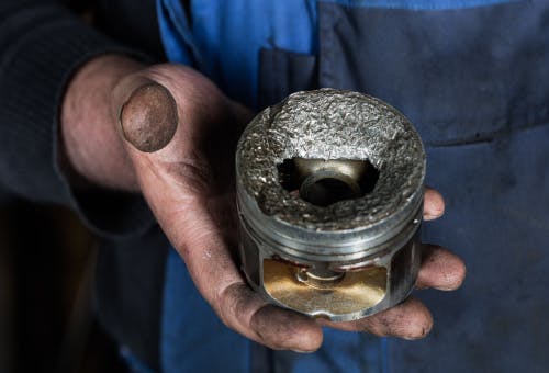
Thus, in engineering speak, "camshaft phasing” refers to the way camshafts are “phased” to ensure that their rotation is synchronised with the positions of the pistons as a function of the rotation of the crankshaft. In simpler language, though, the term “valve timing” is perhaps easier to understand because it implies that the camshaft must open and close the valves at the correct times to prevent potentially severe damage to engine parts from occurring- such as the fatal damage to the piston shown below-

Note that in the context of camshaft phasing the probability of engine damage such as the destroyed piston shown here occurring, depends on the engine type. For instance, in engines known as non-interference engines, the valves and the pistons can never come into contact with each other because of camshaft/crankshaft miscorrelations- even if the camshaft phasing is off by as many as 180 degrees. This is because the clearance between open valves and the tops of the pistons is always large enough to prevent such contact.
By way of contrast, on interference engines, the clearance between open valves and the tops of the pistons is often so small that the pistons can slam into the valves if the camshaft phasing is off by as few as five (or sometimes, fewer) degrees.
Based on the above, it is worth mentioning that determining whether any given engine is an interference or non-interference engine requires access to specific service and repair information, which might not be readily available to non-professional mechanics. Moreover, there is a high likelihood that symptoms such as (among others)-
- no starting conditions
- lack of compression on some or all cylinders
- poor engine performance
- frequent or repeated engine stalling and severe misfires and loud mechanical noises from the valve train that vary with changes in the engine speed are the result of camshaft phasing issues on interference engines.
Be aware though that in many cases, the mechanical damage caused by camshaft phasing failures on some interference engines could be so extensive that it might be more cost effective to replace the engine than to attempt repairs.
Therefore, if you suspect that you might have a problem with camshaft phasing, we strongly recommend that you find an experienced mechanic near you to discuss possible repair options and the estimated costs of each viable repair option because not all possible repair options are financially viable.
