Among the many components that make a vehicle engine run, crankshafts are perhaps the first among equals. So, if you have ever wondered what crankshafts do, how they work, and why they fail, this guide will answer all the questions about the crankshaft in your car’s engine you have ever wanted to ask. Before we get to specifics, though, let us answer this question-

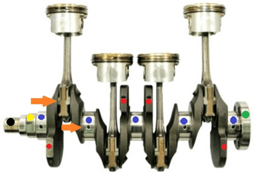
This image shows an example of a crankshaft that is designed for use in a four-cylinder engine, with connecting rods and pistons attached. As with all other crankshafts, this example converts the reciprocating (up and down) motions of the pistons to a rotary motion that powers the vehicle through its drive train. However, to better explain how a crankshaft works, let us look at the different parts of this particular crankshaft and what the coloured dots represent-
Main bearing journals
These are indicated by the blue dots, and in all crankshaft designs, one-half of the diameters of these journals rest inside the engine block, with bearing inserts separating the journals from the engine block. To secure the crankshaft inside the engine, components called “bearing caps” that are fitted with bearing inserts are placed over the exposed part of the journals and are then secured to the engine block with (typically) two bolts, one on either side of the crankshaft journals.
While this arrangement produces enormously strong and rigid engine/crankshaft combinations, the proverbial devil lives in the details. For instance, whether (or not, as the case may be) the crankshaft rotates freely after the bearing caps had been torqued down depends on several things, all of which are equally important to ensure the long-term durability and performance of the crankshaft. Let us look at these things in some detail-
Bearing journal outer diameter

While the actual diameter(s) of the main bearing journals vary between crankshafts intended for different applications, the point is that regardless of the actual journal diameter that applies to any given crankshaft, all the main bearing journals on that crankshaft have to be finished to the same diameter.
More importantly though, if the specified diameter of the main bearing journals on a given crankshaft is say, 40mm, all the journals have to be not only 40mm in diameter, but also have to be 40mm in diameter across the whole width of the journals. This is a particularly important point because bearing inserts are designed so that a clearance of a few hundredths of a millimetre remains between the surfaces of the bearing journals and the bearing inserts after the bearing caps are torqued down.
The purpose of this clearance is to allow pressurised engine oil to form a thin lubricating film between the bearing inserts and the bearing journals. As a practical matter, this lubricating film is the only thing that prevents direct metal-to-metal contact between the bearing journals and the bearing inserts.
Therefore, if the bearing journals were smaller than specified around their full circumference or width, the engine’s lubrication system may not be able to maintain the oil pressure that is required to establish and maintain the lubricating film between the bearing journal surface and the bearing insert.
Similarly, if the bearing journals were bigger than specified around their full circumference or width, the required clearance might be reduced or eliminated. This effectively prevents the lubricating film from separating the bearing journals' surfaces from the bearing inserts, which translates into inadequate lubrication across the bearing journal's full circumferences or widths.
Bearing insert inner diameter
As mentioned elsewhere, bearing inserts are made so that when bearing caps are torqued down a small clearance remains between the bearing journals and the inner surfaces of the bearing inserts, and this clearance is usually within OEM-specified values on new and expertly rebuilt engines.
However, sloppy workmanship during engine assembly by less-expert rebuilders and the use of cheap, sub-standard aftermarket bearing inserts sometimes combine to produce situations where the required clearance is eliminated across the entire width and/or circumference of one or more main bearing journals. In other cases, the clearances might be reduced or eliminated across only parts of one or more bearing journals' width and/or circumference. This prevents the crankshaft from rotating freely, which typically causes the crankshaft to fail in fairly short order. Note that crankshaft failures can occur after a few hundred kilometres of use, but crankshaft failures can also occur within minutes, or even within a few seconds after starting a rebuilt engine for the first time.
Counterweights
These are indicated by the red dots, and their purpose is to counteract the forces that the upward and downward motions of the pistons produce. In all crankshaft designs or applications, the size, weight, and placement of the counterweights are calculated to balance not only the opposing forces created by the pistons and connecting rods exactly to prevent severe engine vibrations but also the effects of both compression and combustion pressures.
This aspect of crankshaft balancing is a highly technical subject, and as such, it falls outside the scope of this guide. Nonetheless, suffice to say that for the purposes of this guide, compression and combustion pressures act like weight, which is factored into the weight of the crankshaft counterweights in all crankshaft designs.
Note that in the example shown here, the counterweights are 180 degrees apart, meaning that they are placed directly opposite each other to make them effective. From a design perspective, this is the simplest arrangement, but for all other engine designs i.e., V6, V8, V10, V12, as well as engines with directly opposed cylinder banks (aka Flat, or Boxer engines), or engines with unequal numbers of cylinders, the design and placement of counterweights becomes hugely complicated.
Nonetheless, some factors in this calculation include (among many others), the following-
- The angle of separation between the cylinder banks
- The size, weight, and diameter of the pistons
- The length and weight of the connecting rods
- The crankshaft’s stroke length
- The engine’s firing order
- The static compression ratio
- The dynamic compression ratio
- The pressure created by the combustion of the air/fuel mixture at various throttle openings
- The engine’s volumetric efficiency, or put differently, how well the engine “breathes”
Overall, all of the above factors play equally important roles in crankshaft balancing and if the designers of a new crankshaft get all of these factors right, such a well-designed crankshaft will provide many years of vibration-free service.
Crankshaft stroke
This is indicated by the vertical distance between the points of the two orange arrows, but in practice, this distance varies greatly between crankshaft designs and applications.
In terms of practicalities though, the stroke acts like a lever, with the load being at the centre of the line formed by the main bearing journals, and the fulcrum being the centre of each big-end bearing journal. Note that for the sake of convenience, we will refer to the journals where the connecting rods attach to the crankshaft as “big-end bearing journals”
To complete the lever analogy, the force that is applied to the crankshaft is supplied by the force created during combustion. As a practical matter, then, the torque an engine develops at any given engine speed and throttle opening is directly related to the relationship between the force applied, and the length of the lever, i.e., the length of the stroke.
Put differently, this means that even if the input force (compression pressure) remains the same in all cases, the longer the stroke is, the more torque an engine develops because the “lever” is longer. However, the longer the stroke becomes, the lower an engine’s maximum RPM becomes because the lever takes longer to complete an engine revolution.
Conversely, the shorter the crankshaft stroke becomes, the less power an engine develops but a short stroke allows for much higher maximum RPM limits because the lever completes an engine revolution in less time. As a practical matter, though, the enormous amounts of energy stored in a rapidly rotating crankshaft assembly replaces much of the lower torque values a short stroke produces, which leaves us with the question of-
What the other dots mean

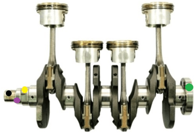
To make it easier to reference what follows, let us consider the image at the beginning of this article again, but with the previously discussed dots removed for clarity. Here is what the other dots represent-
- The green dot indicates a flange that is partly inside the engine, and partly outside the engine. On the one hand, this flange provides a sealing surface for an oil seal that prevents the oil from splashing out of the engine. On the other hand, the rear surface of this flange serves as an attachment point for the flywheel/clutch assembly on manual vehicles, or the flexplate/torque converter assembly on automatic vehicles
- The yellow dot (in this example) features two flat surfaces that engage with the oil pump. Note that in some cases, this part of the crankcase accommodates either a gear that drives the oil pump or a sprocket that drives the timing chain
- The purple dot indicates a part of the crankshaft that provides a sealing surface for an oil seal that prevents the engine oil from splashing out of the engine
- The black dot indicates the part of the crankshaft where the harmonic balancer (aka crankshaft pulley) fits onto the crankshaft. Note that in most crankshaft designs, the harmonic balancer is indexed, or located on the crankshaft with a key while in others, the harmonic balancer is not indexed mechanically, meaning that these harmonic balancers can only be removed and/or installed by using vehicle-specific special tools to maintain the engines valve and/or ignition timing