
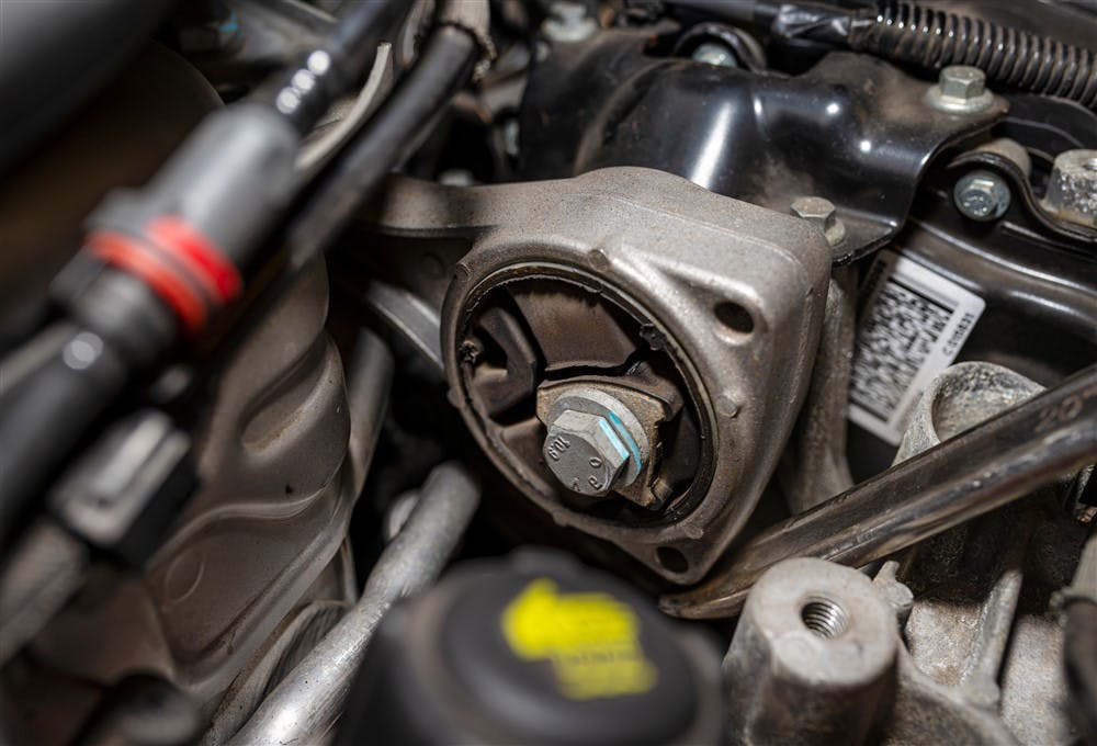
Engine mounts, such as the example shown here, are complex components whose function is to both hold a vehicle's engine and transmission in place in a vehicle and to prevent the engine from transmitting its vibrations and movements to the passenger cabin via the vehicle’s structure.
While explaining what engine mounts are is easy, explaining exactly how engine mounts work is less so, because while all engine mounts perform the same functions, exactly how they do this is different for all vehicles. This is true even in cases where one engine variant is used in several models, as well as in cases where one basic vehicle model is fitted with several different engines to create vehicle variants.
In simple terms, all internal combustion engines produce vibrations when they are in operation, and while we need not delve into the relationships between vibration and harmonics here, we need to bear in mind that all engines produce different vibrational frequencies at different speeds and loads. For instance, 4 and 6-cylinder inline engines typically produce frequencies with higher amplitudes than V6 and V8 engines because V-type engines are inherently more balanced than inline engines. The reason for this is that since torque inputs in inline engines are spaced further apart than on V-type engines, V-type engines rotate more smoothly than inline engines.
However, all internal combustion engines also produce torque to propel the vehicle. As a practical matter, engine torque occurs along the longitudinal centreline of the crankshaft, along which axis the torque is transferred into the drive train. If the engine rotates freely, such as when the transmission is in neutral, the torque the engine develops does not affect the mass of the engine. However, when the transmission engages a gear and the vehicle begins to move, the torque the engine develops causes the engine mass to rotate in a direction opposite to the crankshaft's direction of rotation.
This is a natural tendency of all vehicle engines, and to ensure that all of the engine’s torque is transferred into the drive train, as opposed to being absorbed by the engine mass’s counter rotation, strategically placed engine mounts arrest and absorb the counter-rotation, thus allowing the drive train to absorb the engine's torque to propel the vehicle forward. Consider the image below-
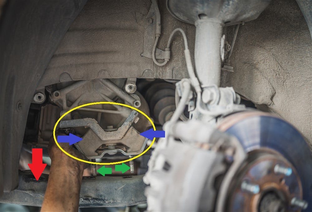
The yellow circle indicates both the design and location of an engine mount in a front-wheel drive vehicle. It should be noted though that although this mount is attached to the end of the transmission, the transmission is attached to the engine to create a single engine mass. Therefore, in this case, the mount shown here is technically an engine mount, although it attaches to the transmission.
In this example, the engine mount itself is circled in yellow, while the blue arrows indicate the actual damping mechanisms, which are simple rubber blocks. The two green arrows indicate the fasteners that attach the mount to the chassis, which in this case, is the longitudinal steel reinforcing bar that is indicated by the large red arrow. Note that, although there are some differences in the layout and design specifics of front-wheel drive vehicles, the basic design and layout of all front-wheel drive vehicles follow the general pattern shown here.
So, in terms of operating principles, engine mounts are flexible, yet somewhat rigid shock absorbers that separate the engine/transmission combination from the vehicle's chassis or frame. On the one hand, engine mounts absorb and damp out normally occurring engine vibrations, while resisting the counter-rotation of the engine mass when the torque that the engine develops increases, at the same time. However, how well (or otherwise) any particular engine mount performs these functions depends on several factors that include, among others, the following-
The placement of all engine mounts
Since all engines naturally tend to rotate around their centres of rotation, i.e., the centrelines of their crankshafts, some parts of a counter-rotating engine develop larger rotational forces than others due to some parts of the engine, such as the cylinder head(s) being located further from the plane of rotation than say, the oil sump.
This being the case, most modern engines have three or sometimes four engine mounts that are placed so that the unequal counter-rotational forces are absorbed and contained equally while preventing the simple counter-rotational force from being converted into a) horizontal lateral forces, or b) vertical axial forces, at the same time. This is saying a lot, but put differently, it simply means that the engine mounts are placed around the engine in a manner that prevents the engine from slipping sideways, or up and down when the engine mounts contain or limit the engine’s counter rotation during high torque applications.
Therefore, the design and placement of engine mounts are based on the physical dimensions of an engine, as well as on the maximum calculated counter rotation an engine can develop as a function of its power output. Other factors that feature in this equation include the weight of the engine/transmission combination, the rigidity of the vehicle’s structure, and the amount of space available around the engine/transmission combination in the engine compartment.
In an ideal car design, all of the above factors would be optimised to produce a vehicle whose passenger cabin would essentially be free of all forms of vibration. However, since producing ideal cars is prohibitively expensive, car manufacturers produce vehicles that exhibit acceptable levels of vibration, as opposed to producing vibration-free vehicles, to minimise production costs.
So, while the placement of engine mounts plays a crucial role in suppressing engine vibrations, the design and construction of individual engine mounts determine the levels of vibration that are transmitted into the vehicle's structure, so let us look at-
Engine mount design
In their most basic form, engine mounts are nothing more than flexible, yet resilient rubber elements that are bonded to steel “frames” to a) contain the rubber elements, and b) make it possible for the mount to be bolted into place between the engine and the vehicle’s structure.
However, since all vehicles and their engine vibrate at different frequencies, car designers take great pains to avoid design mistakes that would allow a condition known as “resonance” to develop. Resonance occurs when two opposing (vibrational) frequencies combine to produce a single, but hugely amplified frequency that could reach potentially destructive levels unless it is damped out, or prevented from developing in the first place.
However, not all resonating frequencies are destructive, but some resonating frequencies can and do produce first and second-order vibrational frequencies in vehicle structures that vehicle occupants can hear and feel at some or all operating conditions. Moreover, some resonating frequencies also interfere with the operation of some classes of vehicle sensors and other equipment such as optical cameras used in some ADAS (Advanced Driver Assist Systems).
To avoid or limit the effects of these kinds of issues, car designers and engineers spend vast amounts of money, time, and energy to develop engine mounts that address the vibration characteristics of each new vehicle model, as well as all possible variants of models that may be fitted with different engine/transmission combinations.
Thus, because each vehicle has unique vibrational characteristics, some engine mounts are hugely complex components that suppress vibrations on three axes, while others are less complicated, but may have composite shock-absorbing elements that consist of two or more different rubber compounds or other types of material, such as polyurethane or neoprene-based materials to absorb unequal frequencies arising from directly opposing sources.
In most cases, engineers are largely able to create engine mounts that address the unique vibrations that originate at specific points in both the vehicle's structure and the "interface" between the vehicle's structure and its engine/transmission combination. Nonetheless, since engineers have not been able to create vehicles that are inherently free of vibration(s), they instead create and develop engine and transmission mounts that are application-specific.
As a practical matter, this means that even though any two or more given engine mountings appear to be identical in all respects, only the mount that is designed with the correct physical properties, such as its elastic rate, will successfully absorb and damp out vibrations in the application it was designed for. Put differently, this means that engine mounts are generally not interchangeable, even if they appear to be the same, or fit in multiple applications.