This image shows a close-up view of two adjacent lobes on a camshaft, and at a glance, it might appear as if these two lobes are no different from the lobes on any other camshaft based on the fact that ultimately, all lobes on all camshafts open and close the engine valves in all four-stroke engines.
However, while the above statement is true, it is only true in a general sense because as with many other aspects of engine design the proverbial devil lives in the details. In this case, the details involve the rather complex relationship between the shape or more properly, the profile of the cam lobes, and the power delivery characteristics of any given engine. Put differently, this means that the profiles of the cam lobes on any given camshaft play a major role in how much power an engine develops at any given engine speed, engine load, and throttle opening.
Of course, many other factors both contribute to and define an engine's power delivery characteristics, but in the context of this discussion, we only need to focus on the points listed below, all of which are functions of the profiles of cam lobes, which determine all of the following-
- The distance that the valves travel between their fully closed and fully open positions, which plays a major part in determining the flow rate of both the air/fuel mixture, and exhaust gas through the intake and exhaust valve openings in each cylinder
- The number of degrees of camshaft rotation measured from the moment a valve begins to open, to the moment the same valve is again in the fully closed position
- The number of degrees of camshaft rotation that the valves are in their fully open or closed positions
- The number of degrees of camshaft rotation that both the intake and exhaust valves on each cylinder are open, albeit partially, and only very briefly
- Limited space precludes a comprehensive discussion of all or even most of the points listed above but we can do the next best thing, which is to illustrate the characteristics of camshaft lobes listed above on an actual camshaft, so let us look at what the arrows and lines on this example camshaft mean-

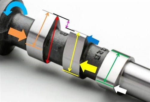
The three camshaft lobes shown here all serve one cylinder of a standard small-displacement four-cylinder engine, but note that the angles, radii, and distances depicted on this camshaft apply only to this particular engine. Before we get to specifics, though, it is important to note that the two lobes on the left each act on an intake valve, while the lobe on the right acts on the exhaust valve. To avoid confusion, we will refer to the two intake lobes as the Orange and Yellow lobes respectively, and to the exhaust lobe as the Green lobe. Note, also, that the large blue arrow on the far left indicates the camshaft’s direction of rotation when it is installed in the engine.
Having said the above, let us look at what the various arrows and lines on the two intake lobes mean in practice, starting with-
The secondary intake lobe (Orange)
NOTE: Given the direction of rotation of this camshaft, the Orange lobe acts on the secondary intake valve, since it is offset from the Yellow lobe by a significant distance as measured in degrees of camshaft rotation. This offset is indicated by the small purple arrow between the two black lines that mark the tops of both intake lobes. Note though, that a) this distance varies between engines, and b) on some engines, there may not be an offset at all, which is common on engines that have two intake and two exhaust valves per cylinder.
- The long red arrow indicates the total height of the lobe, which may or may not be the same for both intake lobes, depending on the engine. Note also, that depending on whether (or not) the engine has hydraulic valve lifters, there may or may not be a clearance between the bottom of the lobe and the cam follower
- The orange line near the bottom of the lobe indicates the point at which the cam lobe starts to contact the cam follower. There is no contact between the lobe and the cam follower below this line
- The long orange arrow represents the total number of degrees of camshaft rotation that the lobe is in contact with the cam follower while the valve is opening. This also determines the valve lift or distance that the valve travels between its fully closed and fully open positions. The top of the apex (the small radius) at the top of the lobe marks the point when the valve is fully open; the valve begins to close when the lobe begins to rotate away from this point
- The large orange arrow marks a pronounced radius within the overall profile of the lobe. This feature on this particular profile design causes a significant, but temporary increase in the rate at which the valve opens to induce a swirling motion in the air/fuel mixture that had already entered the cylinder through the primary (Yellow) lobe
The primary intake lobe (Yellow)
- The yellow line near the bottom of the lobe indicates the point at which the cam lobe starts to contact the cam follower. There is no contact between the lobe and the cam follower below this line
- The long yellow arrow indicates the total number of degrees of camshaft rotation that the lobe is in contact with the cam follower while the valve is opening. This also determines the valve lift or distance that the valve travels between its fully closed and fully open positions. Note, however, that a) the point of first contact on this lobe occurs earlier than on the Orange lobe, and b) the number of degrees of camshaft rotation during which the lobe acts on the primary intake valve is also significantly larger than on the Orange lobe. The top of the apex (the small radius) indicated by the blue arrow at the top of the lobe marks the point when the valve is fully open; the valve begins to close when the lobe begins to rotate away from this point
- The large yellow arrow indicates a major difference between the Orange and Yellow lobes, this difference being the absence of the pronounced radius within the overall profile of the lobe that is present on the Orange lobe. This causes the primary intake valve to open at a near-constant rate to maximize the flow rate of the air/fuel mixture through the (primary) intake valve as the valve opens
The exhaust lobe (Green)
- The large white arrow indicates a major difference between the exhaust and intake lobes, which is the large radius of the profile apex. This allows the exhaust valve to stay open for longer (than the intake valves) to allow the exhaust manifold more time to scavenge, or “suck” the exhaust gas out of the cylinder
- The two green lines and the arrow that connects them represent the number of degrees of camshaft rotation that the exhaust cam lobe acts on the exhaust valve while the exhaust valve is closing
So, what does this all mean?
Put simply, all of the above means that the shape of the cam lobe profiles in this example are optimized to-
- maximize the flow rates of both the intake air and the exhaust gas through the valve openings
- allow the maximum allowable volume of intake air to enter the cylinders through the intake valves
- allow significant turbulence to be induced in the intake charge in the cylinders through the secondary intake valve to improve combustion of the air/fuel mixture
Note that although the design features of the camshaft lobes described above are not the only factors that determine this particular engine’s thermal efficiency, the combined effects of how camshaft lobes are profiled are among the most important factors that determine any engine’s power delivery characteristics.
Therefore, changing or altering the profiles on a standard camshaft will alter the engine’s power delivery characteristics because the engine will breathe differently. However, as a practical matter, minor modifications to cam profiles like increasing the valve lift might produce some power gains.
In practice, though, small camshaft modifications tend to produce small or limited effects, meaning that any power gains will be small, or may only occur (if at all) at some engine speeds. This is because the profiles of camshaft lobes on any engine are just one item in a “package” of engine design imperatives and considerations, all of which work in combination to define an engine’s power delivery characteristics. Therefore, changing one engine design aspect, like the profiles of the camshaft lobes will necessarily influence the effect of one or more other design aspects, and sometimes, it will do so in unpredictable or undesirable ways.
Thus, camshaft modifications should not be undertaken lightly, or without considering all of an engine’s design aspects that affect its power delivery characteristics. In practice, getting some aspects of camshaft replacements/modifications wrong could potentially cause a camshaft replacement or modification to fail or not to work as expected.
More to the point though, always bear in mind that the costs involved in extensive camshaft modifications on road-going passenger vehicles rarely produce a comparable (or the expected) return in terms of increased engine power, lower fuel consumption, and decreased emissions. Note though, that extensive camshaft modifications typically produce a decrease in engine reliability and increased running/maintenance costs.