
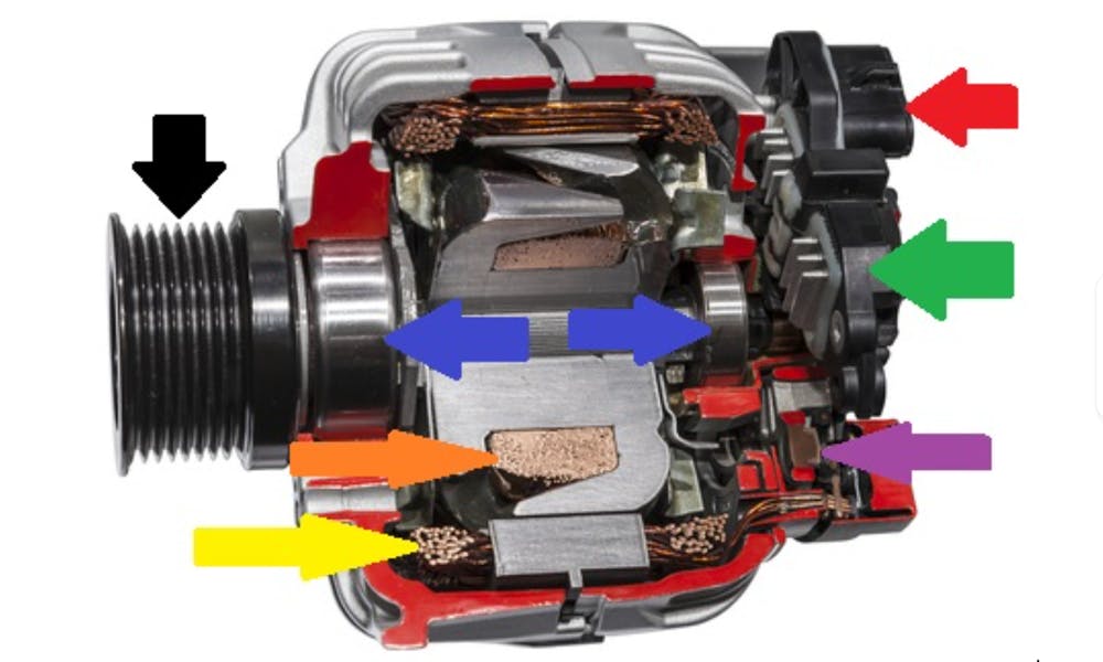
Although a car alternator might look like it's complicated, it is, in fact, a relatively simple device. Moreover, all work in the same way, and all largely contain the same parts. We can save a lot of time by explaining what the arrows in this cut-away view mean. Let us start with-
- The black arrow indicates the drive pulley
- The two blue arrows indicate the support bearings
- The yellow arrow indicates the stator and its copper wire windings
- The orange arrow indicates the rotating rotor and its copper wire windings
- The purple arrow indicates a part of the rectifier
- The green arrow indicates the voltage regulator
- The red arrow indicates the electrical connector on this particular design. Not all alternators have proper connectors; some only have studs that accept cable terminals
Now that we can identify the various components, let us look at what each component does-
The Drive Pulley
The drive belt, which is also known as a "serpentine belt" runs over the pulley to drive the rotor. However, while all drive pulleys look the same on the outside, there are two types of drive pulleys. Here is how they differ-
- Some pulleys are solid, and do not allow the pulley and the rotor to spin at different speeds
- Some pulleys are known as "overrun" pulleys that contain a mechanical clutch. When the engine speed suddenly drops, the clutch disengages automatically. This allows the rotor to slow down without damaging or stretching the drive belt
Support Bearings
The bearings have two functions-
- to reduce friction,and
- to maintain the clearance between the stator and the rotor
This air gap is important because it maintains the magnetic fields that create electricity.
The Rotor
The rotor consists of an iron core, and a single length of copper wire that is wound around it. This is known as a “winding”, which creates a magnetic field when a current passes through it.
This current is known as the “field current”, and its strength determines the strength of the magnetic field. We’ll say more about this in the section about the voltage regulator. Nonetheless, this current is direct current (DC) since it is supplied by the battery through the voltage regulator.
The Stator
The stator does not rotate, but like the rotor, it consists of an iron core. However, unlike the rotor that has a single winding, the stator has three windings that are insulated from each other.
In practice, the poles of three sets of winding are spaced 120 degrees apart. When the rotor’s magnetic field rotates inside the stator, the stator produces an alternating current.
Alternating current flows in two directions. But since cars cannot use such a current, the alternating current is converted into a direct current by-
The Rectifier
As a practical matter, alternators produce three “pulses” of electricity for every revolution of the rotor. However, while stator windings are optimised to “average out” current spikes, they cannot be prevented altogether.
Because of this, rectifiers contain three pairs of diodes- one pair for each winding in the stator. The diodes both convert the alternating current to direct current, and "filter" out alternating current spikes. Diodes work like one-way check valves. They allow current to flow through them in only one direction, which is what creates a direct current.
As a point of interest, the rectifier in the dc battery charger you have at home works in the same way.
The Voltage Regulator
Voltage regulators typically have two power inputs and one power output. One power input is known as the field current supply, while the other is known as the control voltage input. The output is used to supply power from the battery to the rotor winding. Here is how these connections work on alternators that have voltage regulators-
The voltage regulator senses the battery's state of charge through its connection to the battery. When the battery's voltage drops, the voltage regulator increases the current to the rotor winding to create a stronger magnetic field. This creates a stronger charging current.
When the battery’s voltage increases, the regulator decreases the current that passes into the rotor to weaken the magnetic field. This reduces the charging current.
On alternators without voltage regulators, the charging current is managed with an electronic control module. In most cases, this control module is built into the car’s main electronic control unit.