The short answer to this question is that the lobes on camshafts act on the engine valves via one of several methods to regulate the opening and closing of the valves. However, a slightly longer answer involves the design of any particular valve train, which consists of one or more camshafts and all the parts that are required to regulate the opening and closing of the valves, such as cam flowers, hydraulic valve lifters, rocker arms, and pushrods.
In practice, though, there are too many variants of the main valve train designs in use today to allow a comprehensive discussion of each, so to keep things simple, we will only discuss the most common valve train designs in general terms, starting with-
Single Over Head Camshafts (SOHC)

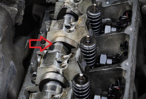
In SOHC (Single Over Head Camshaft) systems, such as the example shown above, a single camshaft (arrowed) acts on all the valves via rocker arms, which were removed in this view for clarity. In SOHC systems where the camshaft is placed directly over the valves, the cam lobes act on components known as “cam followers”, which slide up and down in bores machined into the cylinder head as the camshaft rotates. Since the cam followers are in direct contact with the ends of the stems of the valves, the lobes push on the cam followers to open the valves against the tension of the valve springs as the camshaft rotates.
Single Over Head Camshafts are common on small-displacement engines not only to save on manufacturing costs but also to reduce the engine's size and weight because the valve train works with fewer moving parts. Note also that because a single camshaft acts on all the valves, it is relatively easy for car manufacturers to adapt SOHC valve trains to act on two, three, or even four valves per cylinder to improve the efficiency of small-displacement engines.
Double Over Head Camshafts (DOHC)
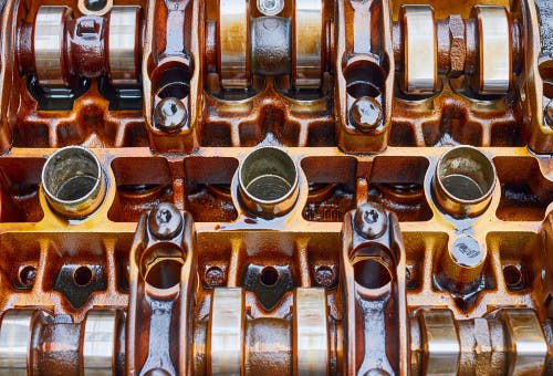
In Double Over Head Camshaft designs such as the example shown here, each cylinder usually has two intake valves and two exhaust valves per cylinder that are placed on either side of the spark plug, which is usually (but not always) located roughly in the geometric center of the cylinder/combustion chamber. In this example, as in most other examples of Double Over Head Camshaft systems, the spark plugs screw into the cylinder head through the tubes (shown here in the middle of the frame) to provide easy access to the spark plugs.
Note that in DOCH systems, the intake valves are arranged along one side of the cylinder head, while the exhaust valves are arranged along the opposite side, with one camshaft located directly above each set of valves. This design has some advantages over SOHC systems, these being the facts that-
- two smaller intake (or exhaust valves, for that matter) allow more intake air to enter the engine, and more exhaust gas to exit the engine than is possible to do with just one intake or exhaust valve per cylinder
- if the two lobes on the intake camshaft that act on the intake valves in each cylinder are slightly staggered, the differential intake air flow rates through these valves induce significant turbulence in the overall intake air charge, which greatly improves the combustion of the air/fuel mixture. In fact, this is a very cost-effective and efficient method of improving both engine performance and fuel economy, while reducing exhaust emissions, at the same time
- the intake charge and the exhaust gas enter and exit the cylinders from opposite sides of the cylinder head(s). This flow pattern greatly improves the flow rate(s) of gases through the cylinders, which has a direct bearing on well (or otherwise) the engine “breathes”
Note that the width, height, and weight of DOCH systems make these valve train designs impractical for use on small displacement engines, on which size and weight /limits reductions are generally more important than the advantages of improved engine breathing characteristics that are inherent to DOHC systems.
Offset rocker arm valve trains
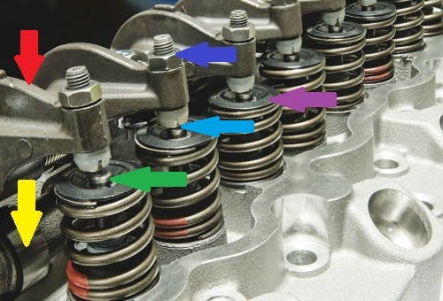
This image shows an example of a valve train that uses rocker arms (aka tappets) to act on the valves. Note that although there are many variations in the design specifics of rocker arm-based valve train designs in use today, the mechanical operating principles of this example (that uses a single overhead camshaft) are representative of the operating principles of all such valve train designs. Let us look at what the arrows in this image mean-
- The yellow arrow indicates the camshaft
- The red arrow indicates a rocker arm
- The green arrow indicates the top of the valve stem; this is the point where the rocker arm applies a downward force on the valve to push it open against the tension of the valve spring
- The purple arrow indicates the retaining ring and locking collets that secure the valve inside the valve spring
- The dark blue arrow indicates the setscrew and lock nut that allows for the adjustment of the valve clearance. In all cases, a specified clearance between the end of the set screw and the top of the valve stem is required to a) allow for the expansion of components, and b) ensure no downward forces are acting on the valve when it is in the closed position
- The light blue arrow indicates the point where the valve clearance is usually (but not always) measured. In some instances, the specified valve clearance is measured at the contact point between the rocker arm and the bottom of the cam lobe
In many designs of this type, a single shaft (not shown in this example) locates and retains all the rocker arms on a common axis, while in others, springs or spring-loaded clips secure the rocker arms to the cylinder head. While the latter methods reduce the mechanical complexity of the valve train somewhat, the downside is that these retention methods can sometimes make it difficult to adjust the valve clearances correctly. Nonetheless, the single biggest advantage that rocker arm-based valve trains have over both SOHC and DOHC valve trains is that-
- adjusting valve clearances is generally easier and less cumbersome than on OHC systems
it is easy for car manufacturers possible to add a second intake valve to each cylinder simply by adding a second cam lobe and rocker arm. This is a common, and cost-effective strategy to increase the performance and overall efficiency of small-displacement engines.
Pushrod-operated valve trains
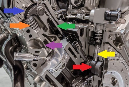
This image shows some detail of a pushrod-operated valve train, which was the most common valve train design across all engines produced by major car manufacturers up until about the late 1970s to the early 1980s when major manufacturers began to introduce OHC systems into the mass automotive markets. Let us look at what the arrows in this image mean-
- The red arrow indicates the camshaft: this location in V-type engines greatly reduces the overall dimensions of the engine. In designs like this, the camshaft is usually driven directly from the crankshaft with gears, although in a few cases, the camshaft is driven directly from the crankshaft with a timing chain
- The yellow arrow indicates a valve lifter: in most cases, valve lifters of this type are not adjustable, since they use pressurised engine oil as a kind of spring that locks the moving parts of the lifter together temporarily. This allows the lifters to exert a force on the valves to open them, and the valve springs in these designs serve only to return the valves to their closed positions
- The orange arrow indicates a valve spring
- The green arrow indicates a pushrod, which transfers the movement of the valve lifter to the rocker arm that ultimately acts on the valve
- The blue arrow indicates a rocker arm
- The purple arrow indicates a valve
One of the major drawbacks of pushrod-operated valve trains is that they are more expensive to produce than OHC valve trains because OHC systems require less machining of the engine block during the production of an engine. Despite the production cost implications though, some modern engines and most notably the LS Series V8 engines made by General Motors use pushrod-based valve trains because this design greatly reduces the engines’ size and weight. In fact, pushrod-based valve trains are a common design feature of the highly modified and hugely powerful engines that power some of the fastest drag racing cars in the world today.
At this point, it is perhaps worth mentioning that contrary to popular belief, OHC systems do nothing meaningful to make modern engines more fuel efficient, powerful, durable, or responsive than pushrod-based valve trains. In practice, the opposite is true: the additional weight of a large number of moving parts, as well as the force required to drive an OHC valve train combine to create a significant parasitic power loss, which necessarily requires the combustion of more fuel to overcome.
However, the increased weight, parasitic power loss, and increased fuel consumption penalties are smaller on large, powerful engines than on small-displacement engines because the rotating assembly of large engines store more kinetic (rotational) energy than the rotating assemblies of small engines do.